Forklift Battery Charging Station Design & Ventilation: The Engineering Guide
Designing an industrial forklift battery charging area requires strict coordination between mechanical ventilation, structural floor planning, electrical distribution, and workplace life-safety regulations. In high-throughput distribution centers and manufacturing plants, non-compliant charging zones introduce catastrophic fire, chemical burn, and explosive hazards.
Historically, facilities operating conventional flooded lead-acid traction batteries were legally required to construct dedicated, blast-resistant charging rooms. These spaces demand high-volume forced air exhaust to purge explosive hydrogen gas (H2), heavy-duty acid-resistant epoxy flooring, spill containment berms, and plumbed emergency eyewash stations.
Today, the rapid industry transition to sealed Lithium Iron Phosphate (LiFePO4) motive batteries is transforming facility infrastructure. By producing zero hydrogen gassing and zero acid fumes, LiFePO4 enables decentralized opportunity charging stations directly adjacent to production docks.
This authoritative technical guide reviews regulatory design standards (OSHA 1910.178, NFPA 1, NFPA 855, and EN 62485-3), presents airflow ventilation calculation formulas, details spill containment protocols, and outlines infrastructure optimizations when retrofitting from lead-acid to lithium.
1. Regulatory Compliance Framework: OSHA, NFPA & European Codes
Industrial lift truck charging installations must strictly comply with national and international workplace safety codes:
| Regulatory Standard | Governing Authority | Core Mandates & Requirements |
|---|---|---|
| OSHA 29 CFR 1910.178(g) | Occupational Safety and Health Administration (USA) | Mandates adequate ventilation for gassing batteries, acid flushing facilities within 25 ft, overhead fire protection, and overhead hoists for safe battery handling. |
| NFPA 1 & NFPA 855 | National Fire Protection Association | Limits hydrogen gas concentration to below 1.0% by volume (25% of the LEL). Mandates continuous mechanical ventilation or interlocking hydrogen gas detection. |
| EN 62485-3 / DIN EN 50272-3 | European Committee for Electrotechnical Standardization (CENELEC) | Specifies safety requirements for secondary batteries used in electric industrial trucks, detailing air extraction calculation formulas and spark-proof electrical fittings. |
| ANSI / ISEA Z358.1 | American National Standards Institute | Requires emergency eyewash and deluge shower stations capable of delivering 15 minutes of uninterrupted flushing water with hands-free activation. |
2. Hydrogen Gas Ventilation: Formulas & Engineering Calculations
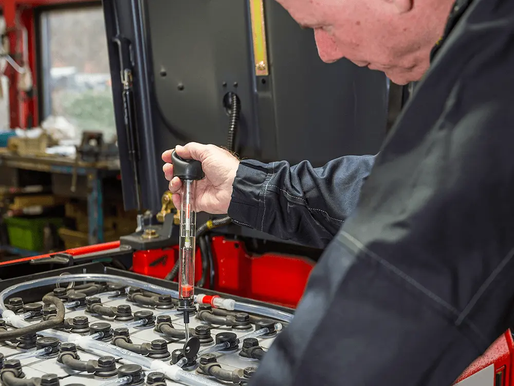
During the final charging stage of flooded lead-acid batteries (the electrolysis phase), water (H2O) splits into oxygen and hydrogen gas. Hydrogen has a lower explosive limit (LEL) of 4.0% by volume in air. Regulatory bodies enforce a maximum allowable ceiling of 1.0% hydrogen accumulation (25% LEL) to prevent violent deflagrations triggered by electrical contactor arcs or static sparks.
A. Standard Airflow Extraction Formula (EN 62485-3)
Mechanical engineers calculate the required minimum exhaust airflow (Q) in cubic meters per hour (m³/h) using the standardized formula:
Q = 0.05 × n × I_gas × C_nom × 10^-3 × f_s

Where:
• Q = Required exhaust airflow rate (m³/h)
• n = Total number of lead-acid cells charging concurrently
• I_gas = Gassing current coefficient (typically 20 mA/Ah for standard flooded cells)
• C_nom = Nominal ampere-hour capacity of the battery pack (Ah)
• f_s = Safety factor (typically 5 to account for ambient temperature and dilution margin)
For a facility charging twenty 48V 600Ah lead-acid batteries (480 total cells), required continuous ventilation frequently exceeds 1,800 to 2,500 CFM (3,000 to 4,200 m³/h) of dedicated spark-proof mechanical exhaust, resulting in substantial winter heating and summer HVAC conditioning losses.
B. The LiFePO4 Infrastructure Revolution: Zero Hydrogen Gassing
Sealed industrial LiFePO4 lithium batteries operate within an entirely hermetic chemical system. During both standard and 1C high-rate fast charging, LiFePO4 produces zero hydrogen gas emissions and consumes zero water.
Engineering Consequence: Converting a warehouse fleet to LiFePO4 completely eliminates the regulatory requirement for expensive explosion-proof exhaust fans, hydrogen gas sensors, and ducting systems. Standard warehouse building ventilation is fully sufficient.
3. Facility Physical Layout: Centralized Room vs. Distributed Opportunity Stations
Selecting battery chemistry dictates the physical architecture of material handling logistics:
A. Legacy Centralized Battery Changing Rooms (Lead-Acid)
- Floor Footprint: Demands 2,000 to 5,000 sq. ft. of prime indoor real estate dedicated to battery racks, cranes, and roller beds.
- Transit Waste: Forklifts must travel off the operational floor to the battery room up to 3 times per day, consuming 15–25 minutes of driver labor per swap.
- Chemical Containment: Requires seamless acid-resistant polyurethane/epoxy coatings and 6-inch concrete containment curbs with acid-neutralizing pillows.
- Water Supply: Requires dedicated reverse-osmosis or deionized water piping for weekly cell topping. (Review our Forklift Battery Maintenance Guide for watering protocols).
B. Modern Decentralized Opportunity Charging (LiFePO4)
- Zero Real Estate Overhead: Fast industrial smart battery chargers are mounted on building support columns directly adjacent to active dock doors and employee break areas.
- Seamless Workflows: Drivers plug in during 15-minute coffee or lunch breaks without leaving their work zone. Battery removal from the vehicle chassis is never required.
- Clean Environment: Eliminates acid drips, floor etching, and dangerous overhead hoist crane maneuvers.
4. Electrical Power Infrastructure & Charger Sizing
Deploying high-output opportunity chargers—such as our 80V 100A–200A Intelligent Charger or 24V-80V Universal Charger—requires deliberate electrical panel planning:
- Three-Phase Feeder Capacity: Ensure facility transformer panels supply dedicated 3-phase 380V, 400V, or 480V AC distribution with appropriately sized thermal-magnetic circuit breakers.
- Dynamic Load Management: In facilities running 50+ electric forklifts, smart charging networks throttle charging current across the fleet during utility peak demand windows, avoiding expensive demand charge surcharges.
- Safety Grounding & Interlocks: Chargers must incorporate pilot-pin interlocks that prevent power flow until the charging connector (REMA DIN or Anderson SB) is 100% seated in the vehicle receptacle.
5. Complete Motive Power & Retrofit Technical Series
Review our specialized engineering conversion guides for leading material handling fleets:
- Safety Standards: Forklift Battery Safety & Compliance Guide: UL 2580, UN 38.3 & NFPA
- Cold Storage: Cold Storage Forklift Battery Engineering Guide: Sub-Zero Operation
- Charger Selection: Forklift Battery Charger Selection Guide: High-Frequency vs Traditional SCR
- Fleet TCO & ROI: Forklift Lithium vs Lead-Acid TCO & Payback Calculation Guide
- Brand Conversions: Toyota | Linde | Crown | Hyster | Jungheinrich | Heli & Hangcha
6. Request Facility Charging Layout Consultation & Sizing
Whether planning a new greenfield distribution center or converting an existing warehouse from lead-acid swap rooms to distributed lithium opportunity charging, ZOSPOWER engineers provide comprehensive electrical calculations, ventilation audits, and turnkey charger hardware.
Planning a Forklift Charging Station or Transitioning to Lithium?
Contact the ZOSPOWER application engineering team for electrical load calculations, charger placement layouts, and custom drop-in battery pricing.