Catastrophic hydraulic hose failure in high-tonnage electric counterbalanced and reach trucks represents one of the most perilous failure modes in heavy materials handling. Sudden burst events under 250–310 bar operating pressures cause uncontrolled mast free-fall risks, environmental hazmat contamination, high-pressure fluid injection injuries, and unscheduled warehouse shutdowns costing upwards of $12,000 per shift. While routine fleet maintenance has historically relied on reactive visual inspections or arbitrary operating-hour intervals (e.g., replace at 4,000 hrs), modern electro-hydraulic architectures incorporate high-frequency pressure transducer sampling, edge-computed pulse damping decay analysis, and predictive fatigue life tracking. This engineering guide details the physics of Joukowsky water hammer shock waves in high-lift mast circuits, non-invasive digital diagnostic methodologies, and multi-tier CAN-integrated mitigation strategies for 24/7 heavy electric fleets.
1. The Mechanical Physics of Hose Degradation: Pulse Fatigue vs. Static Burst
Industrial forklift hydraulic hoses rarely fail due to continuous static operating pressure. A typical 4-wire spiral reinforced hose (SAE 100R12 / EN 856 4SP) rated for 280 bar working pressure has a minimum burst safety factor of 4:1 (bursting at $\ge 1,120\text{ bar}$). Instead, degradation is driven by transient high-frequency impulse cycling and bending-under-pressure fatigue:
- Joukowsky Water Hammer Shock Waves ($\Delta P = \rho \cdot c \cdot \Delta v$): When an operator rapidly closes a proportional spool valve or releases the lift joystick while lowering a 5-tonne rated capacity load at 0.5 m/s, the kinetic column of descending fluid ($v \approx 8–12\text{ m/s}$ in line orifices) undergoes instantaneous deceleration ($t_{\text{close}} \le 25\text{ ms}$). This triggers acoustic shock wave reflection according to the classical Joukowsky relationship:
$$\Delta P = \rho \cdot c \cdot \Delta v$$
Where $\rho$ is the hydraulic fluid density ($\approx 870\text{ kg/m}^3$), $c$ is the acoustic sonic wave speed in flexible steel-wire elastomer conduit ($\approx 1,100–1,250\text{ m/s}$), and $\Delta v$ is fluid velocity change. A rapid valve slam generates instant dynamic pressure spikes exceeding 380–430 bar—surpassing line relief valve reaction speeds by 15–30 ms. - Micro-Fretting of Inner Wire Braids: Under repetitive transient pressure spikes, the high-tensile steel wire spirals deform radially and relax. Friction between crossing wire layers removes the protective brass coating, creating microscopic fretting fatigue notches. Over 250,000–500,000 impulse cycles, micro-cracks propagate inward to outward.
- Thermal-Elastomer Embrittlement: Heavy duty Class 1 and Class 2 trucks operating in dual-drive fast-cycle distribution hubs experience continuous oil reservoir temperatures of 65°C to 80°C. Nitrile (NBR) and synthetic rubber inner tubes lose plasticizers, increasing the elastic modulus $E$ and accelerating crack formation under mast bend radii ($\le R_{\text{min}}$).
Visual inspection catches fewer than 18% of impending hose failures. By the time outer cover blistering, pinhole weeping, or outer jacket cracking becomes visible to a technician’s naked eye, the structural wire braid has already suffered >85% cross-sectional fatigue rupture. Predictive digital diagnostic monitoring moves fleet safety from guesswork to empirical signal processing.
2. High-Frequency Pressure Transducer Instrumentation & Edge Diagnostics
To detect hydraulic line fatigue and impending burst events before high-pressure rupture occurs, advanced electric forklifts integrate thin-film piezoresistive or ceramic strain-gauge pressure transducers directly into the primary mast lift and tilt manifolds:
| Arquitetura do sensor | Sampling Frequency | Diagnostic Metric Tracked | Failure Mode Signature |
|---|---|---|---|
| Standard Telematics Pressure Sensor | 10 Hz (100 ms period) | Static payload weight, mean lift pressure | Blind to shock spikes (<30 ms); fails to predict bursts |
| High-Speed Piezoresistive Transducer (Edge DSP) | 1,000 Hz – 2,500 Hz | Transient spike peak ($\Delta P_{\text{max}}$), rate of rise ($dP/dt$) | Detects main relief chatter, cavitation voids, surge spikes |
| Dynamic Pulse Damping Decay Monitor | 2,000 Hz continuous burst FFT | Acoustic damping ratio ($\zeta$), volumetric compliance ($C_v$) | Hose carcass compliance loss: stiffening rubber increases resonant frequency $\omega_n$ |
| Differential In-Line Flow/Pressure Fusion | 500 Hz synchronous | $\Delta P$ drop vs. pump RPM volumetric output | Internal liner delamination or localized restriction constriction |
3. Mathematical Signal Processing: Detecting Internal Liner Degradation
As a flexible hydraulic hose ages and its inner steel braid sustains cyclic work-hardening, its hydraulic volumetric compliance $C_v = \frac{dV}{dP}$ decreases significantly. In a healthy hydraulic line, the flexible hose acts as an intrinsic hydraulic accumulator, absorbing high-frequency harmonics generated by the axial piston pump or gear pump meshing.
The acoustic natural frequency $\omega_n$ of the fluid-conduit circuit is defined by:
$$\omega_n = \frac{\pi}{L} \sqrt{\frac{K_{\text{eff}}}{\rho}}$$
Where $L$ is hose length, $\rho$ is fluid density, and $K_{\text{eff}}$ is the effective bulk modulus combining hydraulic oil ($K_{\text{oil}} \approx 1.5\text{ GPa}$) and hose radial elasticity ($K_{\text{hose}} = \frac{E_{\text{braid}} \cdot t}{D_{\text{in}}}$):
$$\frac{1}{K_{\text{eff}}} = \frac{1}{K_{\text{oil}}} + \frac{D_{\text{in}}}{E_{\text{braid}} \cdot t}$$
When the internal elastomer hardens and wire braid strands experience micro-strain locking, $E_{\text{braid}}$ increases by 35% to 60%. The vehicle’s edge CAN controller performs Fast Fourier Transform (FFT) on the 2 kHz pressure transducer signal during standard lift operations:
- Healthy Hose Baseline: Broad frequency damping, strong attenuation above 120 Hz, logarithmic decay damping ratio $\zeta \ge 0.28$.
- Impending Failure Precursor: Attenuation vanishes; resonant ripple peaks shift from 85 Hz to 165 Hz; post-valve closure ringing persists for >180 ms instead of damping within 40 ms. This signature indicates imminent braid yield rupture within <150 operating hours.
4. Rainflow Cycle Counting & Cumulative Fatigue Damage (Miner’s Rule)
Modern telematics systems implement the ASTM E1049 Rainflow-Counting algorithm on the live pressure stream. Every hydraulic cycle is cataloged into discrete pressure amplitude bins ($\Delta P_i$) and mean pressure levels ($P_{m,i}$):
Cumulative fatigue damage $D$ is computed in real time using the Palmgren-Miner linear damage hypothesis:
$$D = \sum_{i=1}^{k} \frac{n_i}{N_i}$$
Where $n_i$ is the counted number of pressure pulses in bin $i$, and $N_i$ is the fatigue life cycles to failure at stress range $\Delta P_i$, derived from empirical S-N Basquin curves for 4SP/4SH spiral assemblies:
$$N_i = C \cdot (\Delta P_i)^{-m}$$
When cumulative damage index $D$ reaches 0.80, the vehicle management system (VMS) logs a Level-2 Maintenance Alert via 4G/5G telematics. When $D \ge 0.95$, the controller initiates active protective derating—capping maximum proportional lift speed to 70% and preventing abrupt joystick step-commands to eliminate destructive shock transients until scheduled hose change-out.
5. Active Electro-Hydraulic Mitigation Strategies
Preventive diagnosis must be coupled with active closed-loop electro-hydraulic software control to minimize stress on flexible conduits:
- S-Curve Proportional Deceleration Clamping: When the joystick is instantaneously returned to neutral from full lower or full lift, the hydraulic controller overrides raw operator input. It enforces an exponential S-curve deceleration ($t_{\text{ramp}} = 80–120\text{ ms}$), holding $\frac{dv}{dt}$ below $15\text{ m/s}^2$ and curbing Joukowsky shock spikes by up to 74%.
- Proportional Pressure Relief Cushioning: Rather than relying solely on high-inertia mechanical spring-loaded relief valves, an electro-proportional pilot valve bleeds transient peak energy into the low-pressure tank line whenever $dP/dt \ge 4,500\text{ bar/s}$ is sensed by the transducer.
- Velocity Fuse Velocity Limiting: Direct-mount cartridge velocity fuses at the base of primary lift cylinders provide physical catastrophic rupture protection. If line pressure collapses due to a severe hose burst, the instantaneous drop in downstream backpressure triggers the velocity fuse to seal shut within 12 ms, locking the mast in place and preventing fatal carriage collapse.
6. ZOSPOWER Engineering: High-Current Electric Fleets & Hydraulic Symbiosis
ZOSPOWER industrial lithium battery systems interface seamlessly with modern forklift telematics via dual CAN 2.0B / CANopen protocols. By correlating high-frequency hydraulic pressure transducer spikes with instantaneous traction and pump inverter DC bus currents ($I_{\text{peak}} \ge 450\text{ A}$), ZOSPOWER smart battery management systems provide predictive fleet insights:
- Hydraulic Mechanical Overload Flagging: Detects when operators attempt to lift loads exceeding rated capacity or when mast channel friction/bearing bind forces the hydraulic pump into continuous relief bypass.
- Zero Voltage Sag During Pump Motor Start: Ultra-low internal resistance lithium chemistry ($R_{\text{int}} < 8\text{ m}\Omega$) ensures steady DC bus voltage to electro-hydraulic proportional valves, preventing valve spool flutter and erratic pressure cycling.
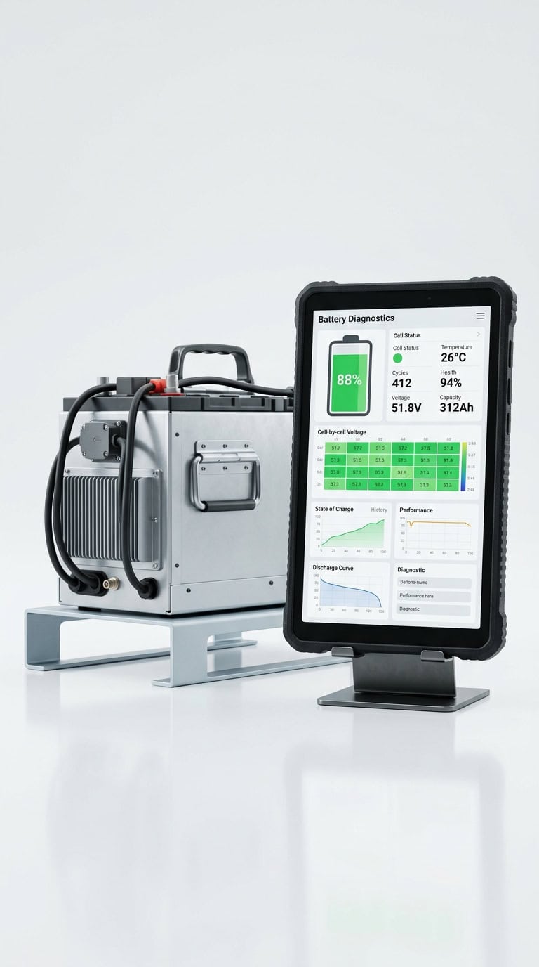
- Integrated Fleet Diagnostic Telematics: Synchronizes hydraulic fatigue health scores with lithium battery lifecycle metrics on unified cloud dashboards.
Upgrade Your Fleet to Predictive Electro-Hydraulic Reliability
Eliminate catastrophic hydraulic blowouts, mast drop hazards, and costly downtime. Consult with ZOSPOWER power systems and hydraulic integration engineers to deploy CAN-connected lithium solutions with integrated predictive health monitoring for your heavy material handling operations.