In electric counterbalance forklifts, reach trucks, and high-voltage container handlers, the vehicle’s motor controllers and hydraulic inverters incorporate large banks of DC-link filtering capacitors (typically 10,000 µF to 30,000 µF). When an operator turns the ignition key, uncharged capacitors behave as a dead short circuit for several milliseconds. Closing the main DC contactor directly onto these depleted capacitors unleashes catastrophic inrush current surges reaching 1,500A to 3,500A. This instantaneous electrical stress causes severe contactor contact welding, blows internal inverter bus capacitors, and trips nuisance BMS overcurrent alarms. This engineering guide details the mathematical principles, hardware resistor sizing, BMS soft-start state-machine sequencing, and field diagnostic protocols essential for inrush current suppression.
1. The Physics of Capacitive Inrush & Contactor Contact Welding
When an uncharged capacitor is connected directly to a DC power source, the instantaneous current is governed strictly by the loop resistance: I_peak = V_battery / R_loop. In a high-performance Lithium Iron Phosphate (LiFePO4) battery system, total loop impedance (internal cell resistance + cable harness + closed contactor resistance) is typically less than 0.025 Ω.
On an 80V nominal forklift pack, direct contactor closure attempts to push an instantaneous inrush pulse exceeding 3,200 amperes within the first 100 microseconds. The consequences of uncontrolled inrush are severe:
- Contactor Contact Welding: Extreme current density across microscopic surface asperities of the silver-alloy contact tips generates localized temperatures exceeding 1,000°C. The contacts momentarily liquefy and weld shut, preventing the contactor from opening during emergency shutdown sequences.
- Capacitor Foil Degradation: Massive \(I^2 t\) electrical heating degrades the internal dielectric metallization layer of electrolytic or film capacitors, drastically shortening inverter lifespan.
- BMS Hardware Trip: As detailed in our guide on Equilíbrio da potência hidráulica e queda de tensão, high-speed hardware comparators interpret the inrush surge as a direct external short circuit, instantly shutting down the battery.
| Engineering Parameter | Direct Uncontrolled Contactor Closure | Controlled Resistor Pre-Charge Circuit | Vantagem operacional |
|---|---|---|---|
| Peak Inrush Current Spike | 1,500A – 3,500A (Destructive spike) | Limited to 1.5A – 3.0A (Controlled) | Reduces peak electrical shock by 99.9% |
| Main Contactor Tip Wear | Severe arcing, erosion & contact welding | Zero arcing (Zero voltage differential across tips) | Extends contactor mechanical life past 250,000 cycles |
| Inverter Bus Capacitor Stress | Severe thermal shock and foil pinholes | Smooth logarithmic voltage ramp | Protects Curtis, Zapi & Inmotion motor drives |
| BMS Short-Circuit Tripping | High probability of nuisance fault lockouts | Zero nuisance trips during startup | Guarantees 100% first-attempt key-on reliability |
2. Pre-Charge Circuit Topology & Mathematical Sizing Formulas
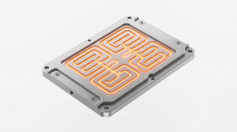
An industrial pre-charge subsystem consists of a high-energy pulse-rated resistor wired in series with an auxiliary solid-state relay or electromechanical pre-charge relay, bypassing the main positive DC contactor:
The voltage charging curve of the inverter capacitor bank is governed by standard RC transient calculus:
V_cap(t) = V_battery × (1 - e^(-t / RC))
Where τ = R × C represents the RC time constant. In industrial drive systems, the standard engineering objective is to charge the capacitor bank to at least 95% of battery terminal voltage before closing the main contactor, which requires an elapsed duration of approximately 3τ (since 1 - e^(-3) ≈ 0.9502).
Single-Pulse Joule Energy Rating Calculation
The total electrical energy dissipated as heat in the pre-charge resistor during each start-up cycle equals the total electrostatic energy stored in the capacitor bank:
E_joules = 1/2 × C_bus × (V_battery)^2
For example, in an 80V heavy-duty forklift with an inverter bus capacitance of 20,000 µF (0.020 F):
E = 0.5 × 0.020 × (80)^2 = 64 Joules
If an operator repeatedly cycles the key switch on and off during pre-shift inspections, the pre-charge resistor must withstand accumulated thermal energy without cracking its ceramic core.
3. Resistor Technologies: Aluminum Housed Wirewound vs Ceramic PTC
Selecting the correct resistor chemistry is vital to prevent thermal runaway inside the battery compartment:
- Aluminum Housed Wirewound Resistors (Preferred): Wound with high-purity nickel-chromium wire encapsulated in silicone and pressed into an extruded anodized aluminum heatsink casing. Rated for 50W to 100W continuous, these units can absorb single pulses of 500 to 2,000 Joules without thermal degradation.
- Positive Temperature Coefficient (PTC) Thermistors: PTC ceramic elements increase resistance exponentially as they heat up. While they inherently limit current during continuous faults, their high thermal inertia requires 30 to 60 seconds of cooling time between starts, which can cause frustrating start-up delays in busy warehouses.
4. BMS Soft-Start State-Machine Sequencing Protocol
In inferior lithium retrofits, pre-charge is controlled by a crude analog timer circuit that blindly closes the main contactor after 500 milliseconds—even if the inverter has an internal short circuit. Zospower traction architectures deploy an intelligent voltage-verified BMS state machine:
- State 0 (Key Off): Main negative contactor, main positive contactor, and pre-charge relay are all de-energized. Insulation resistance monitoring actively verifies floating ground integrity as detailed in our Guia sobre resistência de isolamento e falhas de ligação à terra.
- State 1 (Negative Contactor Closure): Upon key-on signal, the BMS verifies no critical DTCs and pulls in the main negative contactor.
- State 2 (Pre-Charge Engagement): The BMS energizes the auxiliary pre-charge relay, routing current through the aluminum wirewound resistor into the inverter bus.
- State 3 (Voltage Threshold Handshake): An internal precision ADC continuously monitors the inverter DC bus voltage. When
V_inverter ≥ 95% V_battery, the BMS closes the main positive contactor under virtually zero voltage differential. - State 4 (Pre-Charge Disengagement): After a 50 ms dwell time ensuring the main contactor tips are mechanically seated, the pre-charge relay de-energizes. Full operational power is granted to traction and hydraulic systems.
- Fault State (Pre-Charge Timeout): If inverter voltage fails to reach 90% within 2.0 seconds, the BMS immediately disengages all contactors, illuminates a diagnostic warning, and logs a Pre-Charge Timeout DTC.
5. OEM Contactor Integration: Toyota, Linde, Crown & Hyster
Each OEM material handling manufacturer configures motor controller DC bus circuits with distinct capacitance profiles:
- Toyota Material Handling (Zapi/Curtis Drives): Conforme detalhado no nosso Guia de conversão para baterias de lítio em empilhadores Toyota, Toyota’s SAS controller monitors pre-charge timing via CAN bus; failure to reach 90% within 800 ms trips an error 73 code.
- Linde Material Handling (Integrated MOSFET Inverters): Linde electric trucks (Especificações da adaptação para lítio da Linde) feature ultra-low ESR capacitor banks that require high-joule pulse resistors to avoid tripping thermal limiters.
- Crown Equipment (Access 1 2 3 Power Distribution): Crown pantograph trucks (Crown Forklift Lithium Retrofit Guide) integrate electronic contactor drivers; our BMS coordinates with Crown’s native pre-charge logic seamlessly.
- Heavy Port & Terminal Equipment: In massive 80V–96V container handlers (Port Decarbonization Guide), multi-stage dual resistor pre-charge banks suppress inrush currents across dual 500A motor controllers.
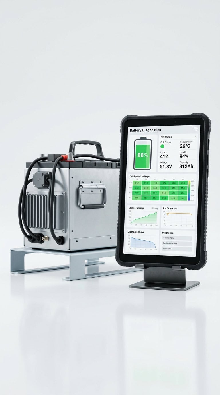
6. Field Diagnostic Protocol for Pre-Charge Timeout Faults
When an electric forklift locks out with a Pre-Charge Failure warning, field service technicians should follow this systematic troubleshooting protocol:
- Ohmic Resistor Verification: Isolate the pre-charge resistor and measure DC resistance with a calibrated multimeter. An open circuit indicates the resistor sacrificed itself due to a downstream short.
- Inspect Inverter DC Bus for Direct Short: Measure resistance across inverter B+ and B- terminals. If resistance reads under 100 Ω with the capacitor discharged, an inverter IGBT phase module is shorted and must be serviced.
- Audit Auxiliary Parasitic Loads: Verify that high-draw auxiliary components (cabin heaters, high-power DC-DC converters, or mast hydraulic solenoids) are not drawing power during pre-charge, stealing current needed to elevate capacitor bus voltage.
- Utilizar com carregadores de alta eficiência: Ensure battery packs are charged smoothly via intelligent resonant charging stations described in our Guia de seleção de carregadores para empilhadores.
Protect Your Fleet Inverters with Zospower Smart Pre-Charge Engineering
Are welded contactors, blown inverter capacitors, and startup fault codes crippling your forklift fleet? Zospower engineers industrial-grade Bateria LiFePO4 systems equipped with active voltage-sensing pre-charge circuits, heavy-duty aluminum pulse resistors, and fail-safe soft-start firmware.
Contact our senior electrical applications engineering team today to audit your forklift inverter capacitance profiles, review contactor ratings, and implement turnkey zero-arcing power architectures.