In high-throughput 24/7 automated warehouses, container ports, and cleanroom manufacturing facilities, autonomous mobile robots (AMRs), automated guided forklifts (AGFs), and automated guided vehicles (AGVs) demand continuous, hands-free opportunity charging. Eliminating manual plug-in cables and hazardous battery swapping rooms requires high-speed automated power replenishment. Intralogistics system architects evaluate two dominant physical charging topologies: high-power resonant inductive wireless power transfer (WPT) and conductive floor/side mechanical copper-beryllium contact pads. Each technology presents fundamentally distinct engineering trade-offs in end-to-end grid-to-battery energy efficiency, misalignment tolerance, cleanroom particulate shedding, explosive atmosphere (ATEX) compliance, capital expenditure, and maintenance lifecycles. This comprehensive engineering guide evaluates electromagnetic resonance physics, contact contact resistance wear mechanisms, thermal management, and functional safety standards governing automated forklift opportunity charging in compliance with ISO 3691-4, IEC 61980, and UL 2594 standards.
1. Charging Physics: Magnetic Resonant Coupling vs. Conductive Metal Interface
The operational capabilities and efficiency limitations of autonomous charging systems stem from their underlying electrical physics:
- Resonant Inductive Wireless Power Transfer (WPT): Operates via high-frequency electromagnetic field coupling between a stationary primary ground transmitter coil and a secondary receiver coil mounted beneath the AGV chassis. Operating at frequencies tuned between $20\text{ kHz and }85\text{ kHz}$ (SAE J2954 standard), resonant tank circuits compensate for large magnetic leakage inductance:
$$f_{res} = \frac{1}{2\pi \sqrt{L_{leak} \cdot C_{comp}}}$$
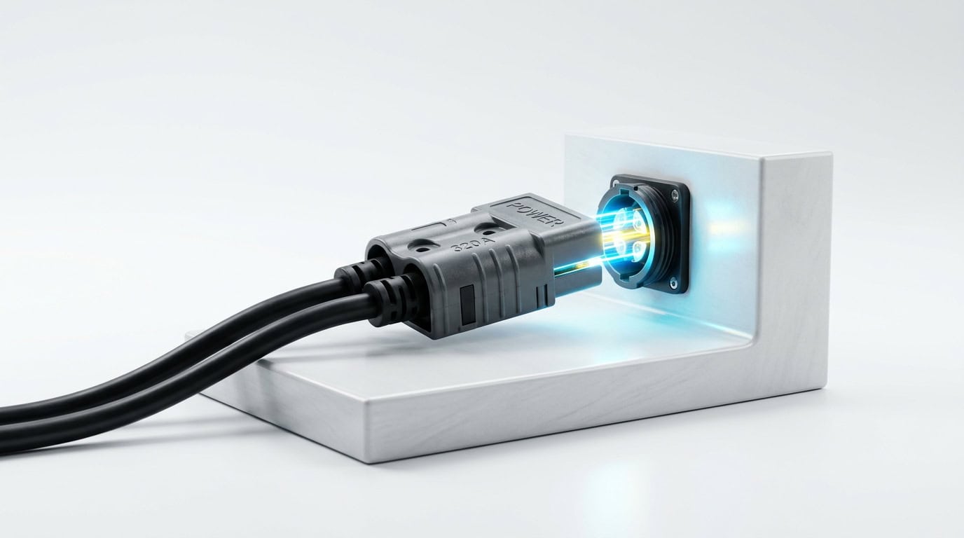
Power transfers across an air gap of $30\text{ mm to }150\text{ mm}$ via mutual magnetic flux ($\Phi_m$), completely eliminating physical contact wear, electrical sparks, and floor obstacles. - Conductive Floor / Side Copper Contact Pads: Relies on direct physical galvanic contact. An automated spring-loaded or pneumatically actuated collector brush shoe assembly (using copper-beryllium $CuBe$ or silver-graphite contacts) extends from the vehicle chassis to press against stationary floor-mounted or wall-mounted copper/brass conductor rails. Contact resistance is governed by contact normal force ($F_N$) and constriction resistance:
$$R_{contact} = \frac{\rho_{bulk}}{2a} + \frac{\sigma_{film}}{A_{true}}$$
Achieving less than $1.5\ \text{m}\Omega$ interface resistance requires maintaining continuous contact normal pressure ($F_N > 25\text{ N}$) across clean metal surfaces.
2. Comprehensive Architectural & Performance Comparison
The matrix below contrasts the operational and technical characteristics of high-capacity inductive wireless systems against conductive contact pads across industrial vehicle deployment criteria:

| Engineering Attribute | High-Power Resonant Inductive Wireless (WPT) | Conductive Copper-Beryllium Floor/Side Pads |
|---|---|---|
| End-to-End Electrical Efficiency | 88% to 92% (High-frequency inverter, coil ESR, and rectifier losses). | 96% to 98% (Near-zero interface resistance; pure conduction). |
| Continuous Charging Power Range | 3 kW to 12 kW (Higher power requires bulky, water-cooled coils). | 5 kW to 45 kW (Up to 300A-500A continuous charging current). |
| Mechanical & Spatial Tolerance | High ($\pm 50 ext{ mm}$ lateral/longitudinal misalignment; $30 ext{ mm to }100 ext{ mm}$ vertical gap). | Strict ($\pm 10 ext{ mm}$ positioning; requires precision AGV docking guidance). |
| Cleanroom Compatibility (ISO Class 3-6) | Superior (Zero physical friction; 100% particulate-free operation). | Poor (Mechanical wiping generates micro-conductive metallic wear debris). |
| Hazardous Atmosphere Safety (ATEX/IECEx) | Intrinsically spark-free; certified for Zone 1/21 flammable vapor/dust areas. | Risk of micro-arcing during pad disconnect under residual current. |
| Floor Ingress & Environmental Sealing | IP67 / IP69K (Submersible; unaffected by water, ice, oil, or chemical washdown). | IP20 to IP44 (Vulnerable to floor dirt, pallet debris, and chemical corrosion). |
| Component Wear & Maintenance Lifespan | Zero mechanical wear; 10+ year maintenance-free solid-state lifespan. | Contact brush shoes wear down; requires replacement every 6 to 12 months. |
| Capital Cost (BOM & Infrastructure) | High initial cost (Resonant inverters, ferrite plates, and secondary rectifiers). | Low to moderate capital cost (Simple copper plates, contactors, and spring linkages). |
3. Conductive Contact Pad Mechanics: Friction, Arcing & Wear
Conductive charging pads remain the dominant choice for heavy 3.0-ton to 10-ton automated counterbalance forklifts requiring ultra-fast 1C to 2C opportunity charging (200A to 400A DC). However, mechanical interface design dictates reliability:
- Arc Prevention via Zero-Current Disconnect State Machine: If an AGV drives away while hundreds of amperes are flowing across copper pads, severe electrical arcing will pit and vaporize the contact faces. Systems must integrate digital CAN-bus interlocks:
$$ ext{AGV Move Request} \longrightarrow ext{Charger Inhibit Current (0A)} \longrightarrow ext{Open DC Contactor} \longrightarrow ext{Retract Pad Linkage} \longrightarrow ext{Traction Enable}$$
The vehicle traction drive is hard-locked until the charger confirms current has dropped below 0.5A and contactors have opened within 15 milliseconds. - Self-Cleaning Wiping Geometry: Floor pads feature ramped lead-in angles and abrasive wiper strips. When the AGV’s collector shoe slides across the plate, the mechanical wipe removes surface oxide films and dust before high-current charging begins.
- Floor Obstacle & Pedestrian Safety: Floor-embedded copper rails present trip hazards and risk accidental short circuits if a metal tool drops across them. Advanced floor pads feature dead-front segmentation: the charging plate remains completely de-energized (0V) until an authorized AGV docks, establishes RFID / NFC proximity authentication, and requests voltage.
4. Inductive Wireless Physics: Misalignment Tolerances & Thermal Loss
For cleanroom wafer fabs, pharmaceutical suites, or food processing freezers where physical contact pads are prohibited, resonant wireless power transfer excels:
- Foreign Object Detection (FOD) & Live Object Protection (LOP): High-frequency alternating magnetic fields ($B > 100\ \mu\text{T}$) induce eddy currents in stray metal objects (screws, paperclips, foil wrappers) left on the charging pad, heating them to over $120^\circ\text{C}$ within seconds. Modern WPT pads integrate multi-channel differential inductive sensor arrays and thermal infrared sensors that shut down power within 50 milliseconds upon detecting stray metal.
- Magnetic Flux Shielding & Human Exposure (ICNIRP Guidelines): High-power magnetic fields must not radiate into the vehicle payload or operator zones. Transmitter and receiver coils are backed by high-permeability sintered ferrite plates (MnZn) and aluminum reflection backplates, containing 99% of stray magnetic flux within the airgap and keeping human exposure safely below the ICNIRP 2010 limit ($27\ \mu\text{T}$).
- Misalignment Compensation via Dynamic Frequency Tuning: As an automated reach truck docks, parking errors of $\pm 40\text{ mm}$ alter coil mutual inductance ($M$). The primary resonant inverter dynamically shifts switching frequency ($79\text{ kHz to }90\text{ kHz}$) and adjusts phase-shift PWM duty cycles to maintain constant charging current without thermal derating.
5. ZOSPOWER Automated Charging Integration for Modern Fleets
ZOSPOWER engineers seamless automated opportunity-charging solutions customized for both conductive and wireless AGV architectures:
- High-Rate LiFePO4 Chemistry Resilience: Our automotive-grade prismatic LiFePO4 cells are chemically formulated for continuous high-rate opportunity charging (1C continuous, 2C peak burst). The cells endure short 3-minute to 10-minute micro-charges throughout the shift without dendrite formation or accelerated capacity fade.
- Integrated CAN-bus Charging Controller: Dedicated onboard communication controllers bridge the vehicle’s BMS directly to the charging station via SAE J1939, CANopen, or industrial wireless (Wi-Fi/Bluetooth). The BMS commands real-time Dynamic Charge Current Limits (DCCL), optimizing charging speed according to instantaneous cell temperature and SOC.
- Comprehensive Drivetrain Synergy: From ソリッドステートPDUのアーキテクチャ ~へ cloud-connected SOH telematics, ZOSPOWER automated charging systems ensure 24/7 autonomous fleet availability with zero manual intervention.
Electrify Your Autonomous Fleet with ZOSPOWER
Whether automating a high-density warehouse with floor copper contact pads or deploying cleanroom AGVs with hermetic inductive wireless power, ZOSPOWER delivers world-class industrial batteries, charging hardware, and functional safety engineering.
Contact our autonomous vehicle applications team today to evaluate charging station layouts, calculate opportunity charging power balances, and configure custom LiFePO4電池 solutions for your AGV fleet.