Moderne elektrische Gegengewichtsstapler und Schwerlast-Schubmaststapler gewinnen bei schneller Verzögerung, beim Befahren von Gefällesrampen und beim Absenken des Mastes mit hoher Traglast erhebliche kinetische und potenzielle Energie zurück. Wechselstrom-Induktionsmotoren und Permanentmagnet-Synchronmotoren (PMSM) fungieren beim Bremsen als leistungsstarke elektrische Generatoren und speisen Hunderte von Ampere regenerativer Gegen-EMK-Energie zurück in den Hochspannungs-Gleichstrom-Sammelschienenkreis ein. Während Blei-Säure-Batterien eine hohe innere Impedanz aufwiesen und durch Überladung des Elektrolyts nur begrenzte transiente Energie aufnehmen konnten, verfügen Hochleistungs- LiFePO4-Akku Diese Systeme erfordern präzise Spannungsbegrenzungsarchitekturen. Befindet sich die Batterie nahe dem Ladezustand (SOC) von 100% oder sinken die Batteriekerntemperaturen unter den Gefrierpunkt, drosselt das Batteriemanagementsystem (BMS) den Ladestrom oder unterbricht ihn vollständig, um katastrophale Überspannungen oder Lithiumplattierung zu verhindern. Ohne geeignete Brems-Chopper-Widerstände und dynamische Spannungsbegrenzung würden unkontrollierte Gleichstrom-Bus-Spannungsspitzen die IGBT-Module des Motorumrichters sofort zerstören oder plötzliche Unterbrechungen der regenerativen Bremsung auslösen, was zu kritischen Risiken durch außer Kontrolle geratene Fahrzeuge führen würde. Dieser technische Leitfaden befasst sich mit der Thermodynamik regenerativer Energie, PWM-Steuerungstopologien für Bremschopper sowie Architekturen zur batteriegestützten Rückgewinnung kinetischer Energie.
1. Die Dynamik regenerativer Energie: kinetische und potenzielle Leistungsspitzen
In der Hochdurchsatzlogistik stammt die Bremsenergie von elektrischen Gabelstaplern aus zwei unterschiedlichen physikalischen Quellen:
- Kinetische Bremsenergie ($E_k = rac{1}{2} m v^2$): Das Abbremsen eines mit 8 Tonnen beladenen Gabelstaplers von 15 km/h bis zum Stillstand in 1,8 Sekunden erzeugt kurzzeitige Stromspitzen zwischen 35 kW und 65 kW (400 A bis 750 A an einer 80-V-Gleichstromschiene).
- Durch das Absenken des Mastes entsteht potenzielle Gravitationsenergie ($E_p = m g h$): Das Absenken einer 4-Tonnen-Palette aus einer Regalhöhe von 6 Metern in 12 Sekunden wandelt potenzielle Energie in die Regenerationsenergie des Hydraulikmotors um und liefert eine kontinuierliche Leistungszufuhr von 20 kW in den Gleichstromkreis des Fahrzeugs.
- Die Begrenzung der Gleichstrom-Sammelschienenkapazität: Fahrzeug-Wechselrichter enthalten Filterkondensatoren für den Gleichstromzwischenkreis ($C_{bus} ca. 10.000\ \mu ext{F} ext{ bis }30.000\ \mu ext{F}$). Die gespeicherte Kondensatorenergie wird durch folgende Gleichung bestimmt: $$E_c = rac{1}{2} C (V_2^2 – V_1^2)$$ In einem 80-V-System führt eine kleine kinetische Energiespitze von 50 kJ, die in eine 20.000 $\mu$F-Kondensatorbank ohne Batterieabsorption oder dynamische Bremswiderstände eingeleitet wird, dazu, dass die Busspannung über 300 V in weniger als 25 Millisekunden, wodurch Wechselrichter-Schalttransistoren mit einer Nennspannung von 150 V bzw. 200 V leicht durchbrennen.
2. Topologien zur Energiebegrenzung: Direkte Absorption aus der Batterie vs. Brems-Chopper-Widerstand
Um eine Überspannung im Bus zu verhindern und gleichzeitig unter allen Betriebsbedingungen eine zuverlässige Bremsleistung des Fahrzeugs zu gewährleisten, kommen in industriellen Antriebssträngen hybride Klemmarchitekturen zum Einsatz:
Direkte Energierückgewinnung aus Batterien (LiFePO₄-Absorption mit hoher Rate)
Unter normalen Betriebsbedingungen (SOC zwischen 10% und 90%, Batteriekerntemperatur zwischen 15 °C und 45 °C) fungiert der LiFePO4-Akku als außerordentlich effizienter regenerativer Speicher:
- Hohe Ladestromaufnahme (2,0 C bis 3,0 C Impuls): Hochwertige prismatische LiFePO4-Zellen nehmen kurze, 5 Sekunden dauernde regenerative Impulse von bis zu 3C (z. B. 900 A bei einem 300-Ah-Akku) mit vernachlässigbarem Polarisationswiderstand auf.
- 12% bis 18% – Verlängerte Lebensdauer bei Schichtbetrieb: Durch die direkte regenerative Energierückgewinnung wird während typischer Bestückungszyklen eine beträchtliche Menge an Energie zurückgewonnen, wodurch der Ladebedarf aus dem Stromnetz sinkt und die Betriebszeit zwischen den Zwischenladungen verlängert wird.
Brems-Chopper und dynamische Widerstandsklemmung
Wenn die Batterie keine regenerative Energie aufnehmen kann, wird automatisch ein spezieller Chopper für die dynamische Bremsung (IGBT-Schalter + Hochleistungswiderstand) aktiviert:
- Vollständige Batteriesperre (SOC > 95%): Wenn ein voll aufgeladener Gabelstapler sofort eine lange Lagerrampe hinunterfährt, drosselt das BMS die regenerativen Ladegrenzen auf null, um eine Überspannung der Zellen zu verhindern ($V_{cell} > 3,65 ext{V}$). Der Bremschopper wird über eine Hysterese-PWM-Steuerung aktiviert und leitet überschüssige kinetische Energie als Wärme in Keramikwiderstände mit Aluminiumgehäuse ab.
- Sub-Zero-Kaltstartschutz ($T_{core} < 0^\circ ext{C}$): Bei Temperaturen unter dem Gefrierpunkt unterbindet das BMS das Laden mit hohem Strom strikt, um die Bildung von metallischen Lithium-Dendriten zu verhindern. Der Chopper leitet 100% der regenerativen Energie an externe Bremsnetze oder an die PTC-Heizelemente innerhalb des Akkupakets um.
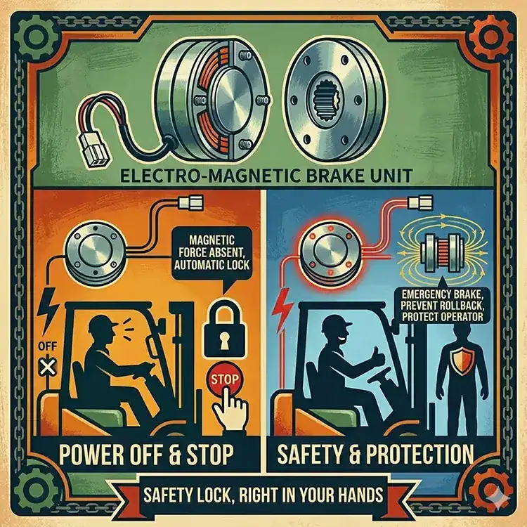
- Ausfallsichere Fahrerbremse: Entscheidend ist, dass dynamische Bremswiderstände dafür sorgen, dass der Fahrer ein gleichmäßiges, konstantes Gefühl beim regenerativen Bremsen erlebt, ohne dass es zu einem plötzlichen Nachlassen der mechanischen Bremskraft kommt – selbst wenn die Batterie vollständig geladen ist.
3. Technische Matrix: Energieabsorption vs. Chopper-Klemmung
Im Folgenden werden die Betriebs- und Sicherheitseigenschaften beider Bremsenergieumwandlungsverfahren gegenübergestellt:
| Betriebsparameter | Direkte Absorption in der Batterie | Dynamischer Brems-Chopper (Widerstandsgitter) |
|---|---|---|
| Wirkungsgrad der Energierückgewinnung | 92% – 96% wurden wieder in den Traktionspark aufgenommen | 0% (100% als Konvektionswärme abgeführt) |
| Verfügbarkeit bei vollem Akku (100% SOC) | Null (das BMS schaltet sich ab, um eine Überladung zu verhindern) | 100% verfügbar (klemmt den Gleichstrom-Sammelschienenstrom kontinuierlich ab) |
| Betrieb bei kalten Temperaturen (<0 °C) | Eingeschränkt, um die Bildung von Lithium-Dendriten zu verhindern | Bei allen Temperaturen voll funktionsfähig |
| Überspannungsschutz für Wechselrichter | Hängt von der Absorptionskapazität der Batteriechemie ab | Hardware-Geschwindigkeitskomparator (Reaktionszeit < 50 μs) |
| Thermische Auswirkungen auf das Fahrzeug | Leichter elektrochemischer Temperaturanstieg (<2 °C) | Hohe Wärmeentwicklung am externen Widerstand (erfordert eine belüftete Montage) |
| Gleichmäßigkeit des Bremspedals | Hängt vom Ladezustand der Batterie und von der Temperatur ab | Konstantes, deterministisches Verzögerungsdrehmoment |
4. Physikalische Grundlagen zur Dimensionierung dynamischer Bremswiderstände und Berechnung des Widerstands
Durch die Berechnung des erforderlichen Widerstands ($R_{brake}$) und der Dauerbelastbarkeit ($P_{cont}$) wird eine zuverlässige Spannungsbegrenzung ohne thermische Überlastung gewährleistet:
$$R_{brake} \le rac{V_{clamp\_threshold}}{I_{regen\_peak}}$$
Dabei ist $V_{clamp\_threshold}$ die Auslösespannung des Gleichstromsammelscheins (typischerweise 88,0 V bei einem 80-V-System, eingestellt unterhalb der Überspannungs-Auslöseschwelle des Wechselrichters von 92,0 V) und $I_{regen\_peak}$ der maximale regenerative Generatorstrom ist (z. B. 400 A). In diesem Beispiel:
$$R_{brake} \le rac{88,0 ext{ V}}{400 ext{ A}} = 0,22\ \Omega$$
Die Impulsenergiekapazität muss die wiederholten Stoppvorgänge im ungünstigsten Fall gemäß EN 1175 auffangen: Ein 5-Tonnen-Gabelstapler, der drei aufeinanderfolgende Notbremsungen aus Höchstgeschwindigkeit durchführt, erfordert eine thermische Energiespeicherkapazität des Widerstands von mehr als 180 Kilojoule (kJ) ohne dass die Oberflächentemperaturen 250 °C überschreiten.
5. Standardarbeitsanweisungen (SOP): Protokolle zur Integration und Wartung
Um die Sicherheit des Bedieners zu gewährleisten und einen Ausfall des elektrischen Systems bei aggressivem regenerativem Bremsen zu verhindern, sind die folgenden Integrationsstandards einzuhalten:
- Koordination der dynamischen Ladestrombegrenzung (DCCL) von BMS: Konfigurieren Sie das BMS so, dass es alle 20 ms die aktuellen DCCL-Grenzwerte über den CAN-Bus überträgt. Wenn der Batterieladezustand (SOC) den Wert 92% erreicht, beginnt das BMS mit einer linearen Reduzierung des DCCL-Werts und weist die Motorsteuerung an, den Arbeitszyklus des Bremschoppers schrittweise zu erhöhen.
- Thermoschutzschaltung mit Widerstand: Die Gehäuse der Bremswiderstände sind mit einem Bimetall-Thermoschalter (Nennwert 180 °C) in normalerweise geschlossenem Zustand auszustatten. Dieser Schalter ist direkt in den Sicherheitskreis der Fahrzeugsteuerung einzubinden; sollte eine längere Bremsung bei Bergabfahrt zu einer Überhitzung des Widerstandsgitters führen, drosselt die Steuerung die Höchstgeschwindigkeit des Fahrzeugs, bevor die Isolierung des Widerstands versagt.
- Verdrahtung mit abgeschirmten verdrillten Paaren und Widerständen: Das Hochgeschwindigkeits-PWM-Schalten (4 kHz bis 8 kHz) in der Chopper-Schaltung erzeugt erhebliche elektromagnetische Störungen (EMI). Verlegen Sie die Kabel der Bremswiderstände in geflochtenen Metallschläuchen und halten Sie dabei einen ausreichenden Abstand zu den Niederspannungsleitungen der Lenkung und der Encoder-Sensoren ein.
- Vierteljährliche Prüfungen des ohmschen Widerstands und des Isolationswiderstands: Messen Sie den Widerstand der Widerstände mit einem kalibrierten Mikroohmmeter, um eine Ermüdung der Drähte oder eine Oxidation der Elemente festzustellen, und führen Sie eine Isolationsprüfung mit einem Megohmmeter bei 1.000 V Gleichspannung zwischen den Widerstandselementen und der Fahrzeugmasse durch (Schwellenwert > 100 MΩ).
Ausführlichere technische Einblicke in elektrische Teilsysteme von Hochleistungsstaplern und Sicherheitsstandards finden Sie in unseren entsprechenden technischen Leitfäden unter Gleichstromschütze und magnetische Ausblasvorrichtungen, Pyrosicherungen und die Abstimmung von Gleichstromsicherungen, und CAN-Kommunikationsprotokolle für Ladegeräte.
Optimieren Sie die regenerative Bremsung und die Wechselrichtersicherheit mit Zospower
Schützen Sie die Wechselrichter Ihres Fahrzeugs vor verheerenden Überspannungsspitzen, verlängern Sie die Betriebszeiten im Schaltbetrieb und gewährleisten Sie eine gleichmäßige Bremskontrolle bei Bergabfahrten. Zospower liefert maßgeschneiderte LiFePO4-Batteriesysteme, die auf eine hohe kinetische Energieabsorption, eine automatisierte, CAN-basierte DCCL-Regelung im geschlossenen Regelkreis sowie integrierte Chopper-Lösungen für die dynamische Bremsung ausgelegt sind.
Wenden Sie sich an unsere Ingenieure für Antriebsstrang, Bremssysteme und Energierückgewinnung